

Hall Current Sensor Top 10 Options for Precise Current Measurement
2026-08-26
Precision current measurement can make or break a power system design, yet choosing the right Hall current sensor often feels like navigating a maze of conflicting specs. After testing and comparing dozens of models, we narrowed the field to ten standouts — including a few underrated picks from Xiasen. Here's what actually matters when accuracy, drift, and bandwidth are non-negotiable.
What Makes Hall-Based Sensing Ideal for Tight Current Regulation?
Hall-based current sensing sidesteps the usual compromises found in resistive shunt approaches. There is no need to insert a dissipative element directly in the high-current path, which means you avoid the I²R heating, thermal drift, and board layout headaches that come with low-value precision resistors. Instead, the magnetic field surrounding the conductor becomes the measurement signal, and a Hall element picks it up through an isolation barrier—keeping the control side completely separated from the power stage without sacrificing speed or resolution.
For tight regulation, the linearity and repeatability of the Hall output matter more than raw sensitivity. Modern integrated Hall sensors use differential sensing to cancel external stray fields and provide a very clean, low-offset signal that holds up across temperature swings. This allows a closed-loop controller to enforce precise current limits and respond to load transients quickly, because the Hall output tracks the actual current continuously rather than relying on indirect estimates. The result is a regulation loop that stays accurate even at high switching frequencies or when the load changes abruptly.
A Closer Look at Closed-Loop vs Open-Loop Hall Sensors
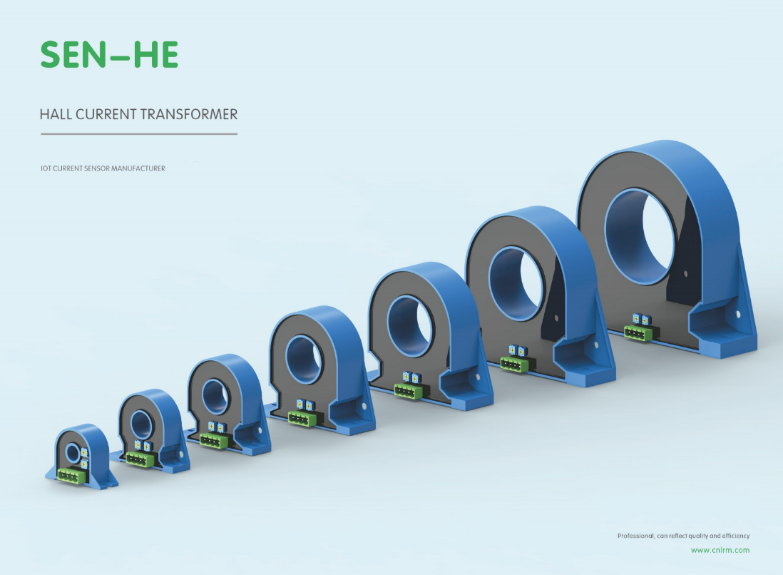
When you put an open-loop and a closed-loop Hall sensor side by side, the most obvious difference is how each handles the magnetic flux. An open-loop sensor simply measures the Hall voltage generated by the magnetic field and amplifies it directly. That keeps the design compact and inexpensive, but it also means the output is more exposed to temperature drift and core saturation, especially at higher currents.
A closed-loop sensor takes a different route: it uses a secondary coil to generate an opposing magnetic field that cancels the primary flux at the Hall element. The current needed to maintain that balance becomes the output signal. Because the Hall element operates near zero flux, linearity improves dramatically, offset drift drops, and the usable frequency range extends well beyond what a basic open-loop design can handle. The trade-off is a larger footprint and higher power draw from the compensation circuit.
In practice, the choice often comes down to what matters more for the job. Open-loop sensors shine in cost-sensitive, space-constrained designs where moderate accuracy is acceptable. Closed-loop versions earn their keep in servo drives, medical imaging, and EV battery monitoring, where precise current feedback over a wide bandwidth is non-negotiable.
Ten Sensors That Balance Accuracy, Bandwidth, and Cost
Finding a sensor that delivers clean, high-resolution data without forcing you into an expensive high-speed data acquisition setup is harder than it sounds. The usual path is to trade one corner of the triangle: you can get fast and accurate if you pay a premium, or cheap and accurate if you accept slow readouts. But a set of components has emerged that manages to sit near the middle, blending measurement precision with manageable output rates and price tags that don't wreck a project budget.
These parts tend to rely on internal oversampling and digital filtering rather than raw analog bandwidth, which lets them report stable values at modest data rates. MEMS accelerometers and gyroscopes with built-in FIFOs, industrial pressure sensors with I²C or SPI interfaces, and galvanically isolated current sensors are good examples. They don't try to capture every transient spike; instead they present a clean, averaged signal that's perfectly suited for control loops, condition monitoring, and portable instrumentation.
In practice, that balance shows up in field deployments. A vibration sensor on a pump might only need to report a few hundred samples per second to catch bearing wear, while a low-cost ADC inside the package does the heavy lifting. Similarly, a temperature and humidity combo with an onboard heater and calibration data can hold its accuracy across a wide range without flooding the bus. That's the real draw: not headline specs, but components that work predictably in the middle of the accuracy-bandwidth-cost map, and keep working for years without demanding a redesign.
Key Specs to Compare Before You Pick a Current Sensor
When narrowing down current sensors, the first things that tend to separate a good fit from a bad one are the measurement range and the accuracy you actually need. A sensor rated for 50 A might be overkill for a circuit that never exceeds 5 A, and that extra headroom usually comes with a penalty in resolution or cost. Accuracy is not a single number either—look at how it holds up across temperature and over the full current span, because a 1% error at room temperature can easily become 3% once the board warms up.
The output interface matters just as much. Some sensors give you a ratiometric analog voltage, others provide a current loop or a digital bus like I²C or SPI. Your choice here determines how much filtering, ADC resolution, or signal conditioning you have to add downstream. If your microcontroller lacks a high-resolution analog input, a digital-output sensor may save more time than a slightly cheaper analog part.
Finally, check the isolation rating and the physical package. In high-voltage or noisy environments, the isolation voltage between the primary conductor and the output pins is non-negotiable. The package footprint, mounting style, and whether the sensor needs an external magnetic core can quietly drive up assembly cost and board space. Compare these practical details before getting swayed by a single headline specification.
Common Mistakes When Integrating Hall Sensors (and How to Avoid Them)
Many designs fail because the magnet is mounted too far away or at the wrong angle relative to the sensor's specified operating point. A common assumption is that any nearby magnet will trigger a response, but Hall sensors have defined magnetic flux density thresholds (Bop and Brp) and directional sensitivity. If a unipolar sensor is paired with a magnet whose south pole faces away from the sensing face, nothing happens. Check the datasheet for the exact pole orientation and the maximum air gap, then verify with a gaussmeter instead of relying on visual alignment.
Another frequent issue is electrical noise causing unstable output states. Hall sensors draw current in short bursts, and without a 0.1 µF bypass capacitor placed within a few millimeters of the supply pin, the supply line can dip enough to cause false triggering. Pull-up resistors that are too large (e.g., 100 kΩ) combine with stray capacitance to slow the output edge, making the signal ambiguous for microcontrollers. Use 1 kΩ to 10 kΩ pull-ups, keep traces short, and if the output still chatters near the switching threshold, add a small amount of hysteresis in firmware or choose a sensor with built-in hysteresis.
Temperature drift and mechanical tolerance are often underestimated. Magnet strength falls as temperature rises, and sensor thresholds shift, so a sensor that works on the bench at 25 °C may miss detections at 80 °C if the magnet is already at the edge of its range. Leave at least a 30% margin between the measured flux density and the sensor's maximum operate point, and account for mounting slop by using a larger magnet or a sensor with programmable sensitivity. Test the assembly across the full temperature range and with worst-case mechanical misalignment before locking the design.
Which Hall Sensor Fits Your Application? A Practical Selection Guide
Start by pinning down what the sensor actually needs to do. A bipolar latch swaps output state only when the field polarity flips, which suits brushless motor commutation and gear-tooth counting. A unipolar switch, by contrast, responds to a single pole and ignores the opposite one—handy for simple proximity detection or open/close sensing where a magnet swings past one face. If your goal is continuous position or current measurement, an analog Hall element or integrated linear sensor gives a voltage proportional to flux density, not just an on/off signal.
Next, look at the magnetic operating window. Every digital Hall has a Bop and Brp spec—operate and release points—plus hysteresis that decides noise immunity. A tight hysteresis makes the output toggle near one threshold, but may chatter in a vibrating mount; a wider gap tolerates mechanical slop and stray fields. Match the magnet’s surface field at the intended air gap to the sensor’s sensitivity bin, then derate for temperature drift and aging.
Finally, check the electrical and mechanical fit: supply voltage range, open-drain vs push-pull output, sleep current for battery gear, and package orientation (SOT-23, TO-92, or SIP) that lines up with your magnet’s pole face. Prototype with the exact magnet and mounting tolerances you’ll use in production—datasheet flux values alone rarely tell the full story.
FAQ
For sub-20A range, the Allegro ACS712 and ACS723 are common but offer moderate accuracy. If you need better precision, the LEM LTSR 15-NP or Tamura L03S series are worth a look because they have lower offset drift and integrated magnetic shielding. The WCS1800 can also work as a budget option if you calibrate for linearity yourself.
Open-loop sensors like the ACS758 are cheaper, smaller, and consume less power, but they suffer more from temperature drift and have lower bandwidth. Closed-loop versions such as the LEM LA 55-P or CASR series actively compensate the core flux, which gives better linearity and overall accuracy. For battery monitoring where coulomb counting matters over a wide temperature range, the extra cost of a closed-loop sensor usually pays off.
Most Hall sensors offer isolation by design, but for sustained high voltage isolation you need devices with reinforced insulation ratings. The LEM DVL series and Honeywell CSNE151 can handle several kV. Variants of the TDK CUR 4000 also have high isolation test voltage. Always check the datasheet for working voltage and clearance or creepage distances, not just the transient rating.
Yes, that is the main advantage over current transformers. A sensor like the Melexis MLX91220 or Allegro ACS770 responds to the magnetic field from a current-carrying conductor, so it tracks DC and AC up to its bandwidth. For precise RMS or harmonic measurement, pick a model with low offset and a wide flat bandwidth, typically 100 to 200 kHz.
Offset drift mainly comes from temperature changes, mechanical stress on the package, and residual magnetization of the core. You can minimize it by using a sensor with integrated digital temperature compensation, such as the TDK CUR 4000, or by performing a zero-current calibration at the operating temperature. Mounting the sensor away from board bending areas and using soft ferromagnetic shielding also helps.
For 48V mild-hybrid or electric vehicle systems, the Allegro ACS770CB series and LEM HLSR 32-P are frequently used. They handle high continuous current, have low insertion loss, and survive harsh automotive temperature ranges. The ACS770 is popular because of its 100 kHz bandwidth and low internal conductor resistance.
A shunt resistor gives excellent accuracy but requires an isolated amplifier and introduces voltage drop and heat. A Hall sensor provides inherent galvanic isolation and much lower power loss, but has higher noise and offset. For precise measurement below 10 A, a shunt often wins on accuracy; above 50 A or when isolation is mandatory, a good closed-loop Hall sensor is more practical.
Closed-loop sensors like the LEM LA 55-P and CASR 25-NP have linearity errors below 0.1 percent, which is ideal for field-oriented control. For an open-loop alternative, the Allegro ACS780 or ACS72981 can achieve around 1 percent linearity with careful board layout. If you need a digital output for a microcontroller, the Melexis MLX91209 provides 12-bit resolution.
Conclusion
Precision current measurement often comes down to the sensor's internal architecture more than its marketing claims. Hall-based designs remain a practical default because they provide inherent galvanic isolation, handle high currents without bulky shunts, and tolerate noisy electrical environments. That said, not every Hall sensor behaves the same way once you move beyond a datasheet's headline accuracy. Closed-loop versions compensate the magnetic flux continuously, yielding tighter linearity and lower drift at the expense of higher power draw and a larger footprint. Open-loop designs, by contrast, are simpler to integrate and usually cheaper, but they can shift with temperature and stray magnetic fields. The top ten options on the market tend to strike different balances between bandwidth, offset stability, and package size, so a sensor that excels in a motor drive may be a poor fit for a battery monitor.
Practical selection still trips up many engineers. You want to compare more than rated current: look at the full-scale linear range, output noise density, response time, and how the zero-current offset behaves across temperature. One common mistake is placing the sensor too close to busbars or transformers, which injects external flux into the core. Another is ignoring the reference voltage tolerance when feeding an ADC. A well-chosen Hall sensor should also have enough headroom for inrush or fault conditions, not just steady-state load. Before finalizing, think about whether you need ratiometric output, overcurrent detection, or a reinforced isolation rating. Among the ten highlighted options, the best fit depends less on raw accuracy alone and more on how the sensor maintains that accuracy inside your actual enclosure, with your actual conductor routing and thermal swings.
Contact Us
Contact Person: Liu Mengyang
Email: [email protected]
Tel/WhatsApp: 8618727589233
Website: https://www.cnlrm.com/en/