

Reliable Shunt Resistor: How to Choose the Right One for Your Application
2026-08-25
Shunt resistors quietly handle some of the toughest jobs in electronics—from battery monitoring to motor control—yet picking the wrong one can silently derail your design. At Milliohm, we know that a “reliable” shunt isn’t just about tolerance or wattage; it’s about matching real-world thermal drift, PCB layout stress, and long-term stability to your exact application. But with so many options and specs to weigh, where do you start? In this post, we’ll strip away the guesswork and give you a practical framework for choosing a shunt resistor that actually holds up when it matters.
Why a Shunt Resistor's Reliability Hinges on More Than Resistance
A shunt resistor often gets treated like a simple passive part: pick the right milliohm value, bolt it in, and move on. But anyone who has chased intermittent drift or unexplained thermal shutdowns knows that resistance is only the starting point. The real story lives in how the resistor shares heat, where the current actually flows through the alloy, and whether the terminations can handle repeated thermal cycling without developing micro-cracks. Two shunts with identical resistance specs can behave completely differently under pulsed loads, simply because one has a low thermal mass and the other spreads heat unevenly across its element.
The geometry of the resistive element plays an outsized role in long-term stability. A flat stamped metal strip may have the same resistance as a precision foil shunt, but its current distribution is rarely uniform at higher frequencies. That non-uniformity creates hot spots that slowly alter the alloy's grain structure, causing the resistance to creep upward over months of service. Meanwhile, the connection interface—whether it uses press-fit pins, soldered leads, or welded copper busbars—introduces its own parasitic resistance that can swamp the intended value if not carefully accounted for during design.
Then there are the environmental factors that quietly degrade performance: humidity ingress along the encapsulation seams, oxidation at the sense terminal joints, and even mechanical stress transferred from nearby components. A shunt that measures perfectly on a lab bench can fail to meet accuracy targets after a year of vibration and temperature swings, not because the resistance changed, but because the sensing path developed a few extra milliohms of contact resistance. Reliability, in the end, comes down to controlling every contributor that sits between the current and the voltage you actually measure.
Matching the Shunt to Your Actual Current Range Without Assumptions
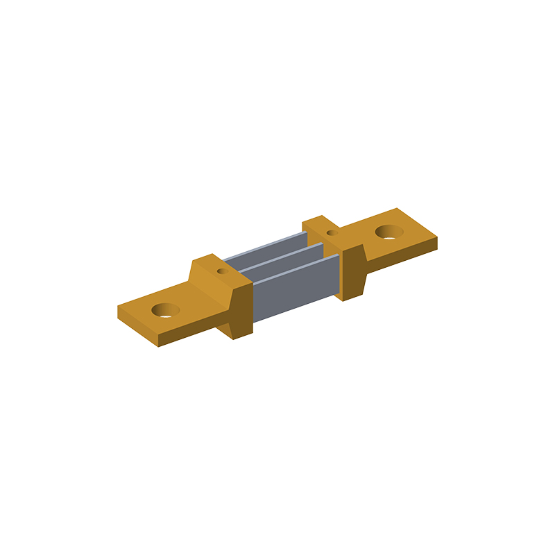
Many designs pick a shunt based on the current sensor's nominal maximum or some worst-case guess. That often results in a resistor sized for a range you never actually use. If your real load stays between, say, 2 A and 8 A but the shunt is rated for 50 A, the voltage drop at 2 A is tiny, leaving the ADC's lower bits swamped by noise. Matching the shunt means first logging the true current envelope over all operating modes, not just peak.
Once you know the typical minimum and maximum currents, size the shunt so the minimum current produces a readable voltage while the maximum stays within the amplifier's linear input range and the shunt's power rating. Don't assume the maximum equals the supply fuse rating. A 20 A circuit may only draw 5 A in normal use, and the shunt should be optimized for the 0.5–5 A span, with a separate protection path for faults.
Also account for transient periods and inrush that are real but brief. You may need a slightly larger shunt to survive short overloads without failing, but that doesn't mean you should optimize steady-state accuracy for those rare events. Use a shunt with a low temperature coefficient and keep the trace resistance out of the measurement loop. The result is a current range that fits the actual application, not an assumption.
Temperature Coefficient Is the Spec That Quietly Erodes Accuracy
You can calibrate a system until every digit lines up on the bench, yet a week later the readings have wandered again. The culprit is rarely a sudden failure—it’s the slow, temperature-driven drift baked into every resistor, voltage reference, and amplifier stage. A part’s temperature coefficient, often buried in a datasheet footnote, describes how much its value shifts per degree Celsius. Over the course of a day, with equipment warming up or a breeze hitting the enclosure, those tiny ppm/°C figures stack into real measurement error that no one notices until it’s too late.
Take a precision current-sense resistor rated at 50 ppm/°C. A 20°C rise—hardly unusual inside a closed chassis—moves its resistance by 0.1%. If that resistor sits in a feedback loop, the gain error compounds through the signal chain. Voltage references are even more temperamental: a 10 ppm/°C part drifts 50 µV per 5°C, which might be half your ADC’s least significant bit. The insidious part is that these shifts don’t look like noise. They look like a slow, believable change in the measurand, so you trust the reading while the error quietly eats your margin.
Designers who chase accuracy learn to treat temperature coefficient not as a marketing bullet point but as a budget item. The first step is reading the fine print—some coefficients are specified only over a narrow range, or they’re parabolic, meaning the worst drift happens at the extremes. Then you either compensate with temperature sensing and lookup tables, or you spend money on low-drift parts and careful thermal layout. Most field returns for “out of spec” instruments trace back to someone ignoring this quiet spec. It never announces itself, but it’s always there, waiting for the room to get a few degrees warmer.
Power Rating and Heat Dissipation Matter More Than the Printed Number
Most people glance at the wattage printed on a speaker or amplifier and assume bigger always means louder or better. That number is only a rough label, not a guarantee of real-world performance. A device rated at 100 watts can easily be outperformed by a 50-watt unit if the 100-watt version struggles to shed heat. Once the voice coil or output transistors get too hot, efficiency drops, distortion rises, and the claimed power becomes meaningless.
Heat dissipation is the hidden bottleneck. A well-designed chassis, heatsink, or airflow path lets a component sustain its output without throttling or degrading. In contrast, a compact unit with a high printed rating may only hit that figure for a few milliseconds before thermal protection kicks in. So when comparing gear, look past the printed number and ask how the design manages continuous thermal load. That tells you more about real capability than any marketing label.
Metal Alloy, Foil, or Wirewound Shunts for Different Field Conditions
Selecting the right shunt technology often comes down to the electrical environment and mechanical stresses present in the field. Metal alloy shunts, typically made from manganin or constantan, offer a low temperature coefficient and stable resistance over a wide range, making them a solid choice for precision current sensing in laboratory or test bench setups where thermal drift must be kept minimal. Their flat, stamped construction also handles pulse loads well, but the resistance values are inherently low, so high-current applications may produce noticeable heat that needs proper sinking.
Foil shunts provide a different balance by embedding a patterned resistive foil on an insulating substrate, which allows for tighter tolerance and lower inductance than bulk metal. This is particularly useful in switching power supplies or motor drives where fast current transients can cause inductive voltage spikes that distort measurements. The thin foil also responds quickly to temperature changes, so in environments with rapid thermal cycling, foil shunts can maintain accuracy better than some wirewound types, though they may require careful mounting to avoid mechanical stress.
Wirewound shunts excel in rugged field conditions with high vibration, shock, or continuous overload. The helical winding increases the resistive path length, enabling standard resistance values from milliohms to several ohms, which is handy when the measured current range varies widely. However, the winding introduces inductance, so they are less suited for high-frequency AC or fast-switching DC circuits unless special non-inductive winding is used. For heavy industrial loads like traction motors or battery banks, a wirewound shunt often survives where a precision foil might crack or a thin metal alloy strip could deform under sustained heat.
Placement, Traces, and Solder Joints Decide Long-Term Shunt Stability
Where you put a shunt resistor and how you route its traces can matter more than the resistor's own tolerance. A current sense resistor placed too far from the amplifier input sees extra parasitic inductance and capacitance. These parasitics turn fast load transients into voltage spikes that corrupt the measurement. Board designers often treat a shunt as a simple two-terminal part, but its real-world behavior depends on the copper around it.
Trace length and geometry directly affect thermal drift and signal integrity. Long, thin traces add series resistance that changes with temperature, shifting the apparent shunt value. They also act as antennas for switching noise. A Kelvin connection with four separate terminals helps, but only if the sense traces run close together and away from high-current loops. Misrouted sense lines pick up magnetic fields from nearby inductors or transformer windings, injecting offset into the readout.
Solder joints are another hidden variable. Uneven solder coverage creates non-uniform current distribution through the shunt element, producing localized heating and long-term resistance drift. Voids under the pad worsen this by forcing current through narrow bridges. Over time, thermal cycling expands and contracts these bridges, causing micro-cracks that gradually increase resistance. A robust layout therefore requires symmetrical pad design, controlled solder paste volume, and verification under actual load conditions rather than just a static resistance check.
FAQ
A shunt resistor converts current into a small proportional voltage drop. By placing a known low resistance in series with the load, you can measure that voltage and calculate the current using Ohm's law. This approach keeps the measurement circuit isolated from high voltage and works well in both AC and DC systems, provided the resistor's value stays stable under load.
Resistance value, power rating, tolerance, and temperature coefficient of resistance usually dominate the decision. The resistance sets the full-scale voltage for your expected current, the power rating must handle continuous plus surge conditions, tolerance affects initial accuracy, and the temperature coefficient tells you how much the resistance shifts as the part heats up. Lead inductance and thermal EMF also become critical in low-level measurements.
Start by deciding the maximum voltage drop you can tolerate or the minimum signal your amplifier can resolve. Use R = V / I, where V is that voltage drop at the maximum current and I is the full-scale current. Then check that the resulting power dissipation I²R stays under the resistor's rated power with some margin, and adjust upward or downward if the voltage drop gets too large for the circuit.
Two-terminal parts have a single pair of connections for both current carrying and voltage sensing, so the measured voltage includes the lead and contact resistance. Four-terminal versions separate the current path from the sense path with Kelvin connections, eliminating those parasitic drops and giving much better accuracy, especially below a few milliohms.
The temperature coefficient describes how much the resistance changes per degree of temperature change. A resistor with a high coefficient will drift noticeably as it self-heats or as ambient temperature changes, producing an error in the calculated current. For stable readings over a wide temperature range, you want a low TCR, typically below 50 ppm/°C for precision work, and ideally a material with a predictable curve.
Many designers look only at the continuous power rating and forget about pulse or surge conditions. A shunt resistor may see brief current spikes that dissipate far more energy than the average load suggests. The part needs to handle those transients without permanent resistance shift or mechanical damage. Also, the rated power is usually specified at a certain temperature and mounting condition, so a tight PCB layout with poor heat spreading can derate the part significantly.
Manganin and constantan are classic choices because they offer low thermal EMF against copper and very stable resistance over time. Metal alloy strips like nichrome or specially processed copper-nickel alloys are common in surface-mount parts for low resistance and good pulse handling. Thick film is cheap but drifts more under stress, so it is usually avoided for precision current sensing unless the current levels are modest.
Keep the sense traces short, matched, and routed as a differential pair to avoid picking up noise. Place the resistor away from hot components and provide enough copper area for heat spreading, because local temperature rise is the main cause of resistance drift. For four-terminal parts, connect the sense traces directly at the resistor pads, not downstream, and avoid running high-current traces near the sense lines.
Conclusion
A dependable shunt resistor is rarely just a low-ohm metal block; its field reliability comes from choices that start well before the solder flows. One of the first missteps is fixating on a nominal resistance value while ignoring the real current window. A part sized too close to its maximum continuous current leaves no margin for inrush pulses or ambient heat, and a part selected from a datasheet headline number may run hotter than expected once derating kicks in. Equally important is the temperature coefficient of resistance—often abbreviated TCR—because even a few parts per million per degree Celsius can quietly shift the measured voltage drop enough to push a precision system out of tolerance. Instead of assuming the printed resistance stays constant, designers should look at the full TCR curve and the shunt's thermal path to the nearest copper pour.
Beyond the datasheet numbers, the physical construction decides whether the shunt stays stable after hundreds of thermal cycles. Metal alloy elements tend to handle pulse energy and low resistance values well, while foil types offer tighter TCR and lower thermal EMF for precision sensing, and wirewound parts can be useful in high-energy or non-inductive configurations depending on the field conditions. However, even the best element underperforms if the PCB placement forces heat into adjacent components or if the sense traces pick up stray voltage drops from high-current paths. Solder joint quality and symmetric pad geometry matter just as much as the alloy recipe: uneven wetting or a long, narrow trace between the shunt and the sense amplifier can introduce milliohm-level errors that look like shunt drift. A truly reliable choice therefore pairs the right material and package with careful layout and thermal management, rather than trusting a single datasheet number.
Contact Us
Contact Person: Yuying Gao
Email: [email protected]
Tel/WhatsApp: +86 18926013721
Website: https://en.milliohm.net/